Speed and torque regulation
The ACS variable-frequency system adjusts motor grid current to control the speed and torque of the connected prime mover.

 Home
About Us
Product
Home
About Us
Product
 Hydraulic dynamometer
Eddy current dynamometer
AC dynamometer
Engine cooling water column
Control and data acquisition system
Engine trolley
Recycling Water System
Hydraulic dynamometer
Eddy current dynamometer
AC dynamometer
Engine cooling water column
Control and data acquisition system
Engine trolley
Recycling Water System
 News
Contact Us
News
Contact Us
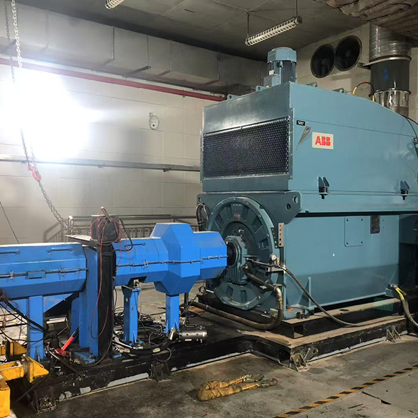
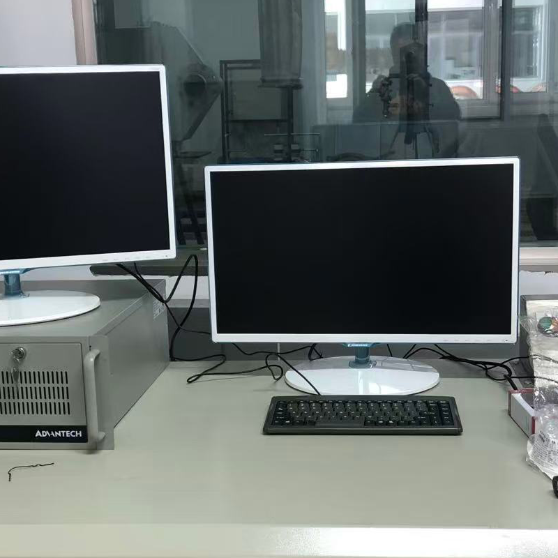
A four-quadrant AC dynamometer system for precise speed and torque measurement and control, with regenerative grid connection and integrated multi-parameter test-cell acquisition.
The CAC series is designed for power testing of engines and other rotating machinery. Its four-quadrant architecture supports controlled operation across both driving and absorbing conditions while the measurement system monitors the variables needed for a complete test.
The ACS variable-frequency system adjusts motor grid current to control the speed and torque of the connected prime mover.
Generated AC power is converted to DC and then converted back to AC for grid connection during absorbing operation.
Torque and speed sensors form part of the standard system architecture for dynamometer feedback and test measurement.
Measure and control speed, torque, temperature, pressure, flow, current and voltage within one test environment.
The standard arrangement combines the load machine, measurement hardware, mechanical interfaces, power electronics and control functions needed to form an integrated AC dynamometer test platform.
AC motor used as the dynamometer load machine
Torque and rotational-speed measurement sensors
Base and flange for connection to the test machine
ACS four-quadrant variable-frequency drive and power distribution
Dedicated AC dynamometer controller
Optional integration with the FC2000 measurement and control system
The CAC system coordinates the AC machine and converter so the dynamometer can apply or absorb load while maintaining the requested test condition.
The engine or rotating machine connects to the dynamometer through the specified base and flange arrangement.
Integrated sensors provide the feedback signals required for measurement and closed-loop control.
The ACS drive regulates current to command dynamometer speed or torque according to the test requirement.
During absorption, generated power is converted through the drive and returned as grid-compatible AC power.
When paired with Hance FC2000, the AC dynamometer becomes part of a broader engine or rotating-machinery measurement system rather than an isolated load device.
Final sensor channels, interfaces, mechanical coupling and control modes should be confirmed for the specific machine under test.
A correctly selected AC dynamometer must match both the mechanical operating envelope and the electrical and facility conditions of the test cell.
Answers to common questions when planning a regenerative engine or rotating-machinery test system.
It applies controlled motoring or absorbing torque to an engine or other rotating machine while measuring speed and torque across the required test conditions.
Four-quadrant operation allows the dynamometer drive to control torque in both rotational directions and to operate in both motoring and power-absorbing modes.
The generated AC power is converted to DC through the ACS converter and then converted back to AC for grid connection.
The supplied product information lists speed, torque, temperature, pressure, flow rate, current and voltage.
Provide the machine type, torque-speed envelope, test modes, rotation direction, duty cycle, mechanical interface, grid conditions and desired measurement channels.
Combine the CAC dynamometer with control, alternative absorber technology and test-cell support equipment.
Share the machine type, torque, speed, test cycle, grid conditions and measurement requirements with Hance.