Accurate testing down to 5% of rating
High-power HDX dynamometers can precisely test low-power engines without switching to a smaller absorber, reducing the number of units required on the floor.

 Home
About Us
Product
Home
About Us
Product
 Hydraulic dynamometer
Eddy current dynamometer
AC dynamometer
Engine cooling water column
Control and data acquisition system
Engine trolley
Recycling Water System
Hydraulic dynamometer
Eddy current dynamometer
AC dynamometer
Engine cooling water column
Control and data acquisition system
Engine trolley
Recycling Water System
 News
Contact Us
News
Contact Us
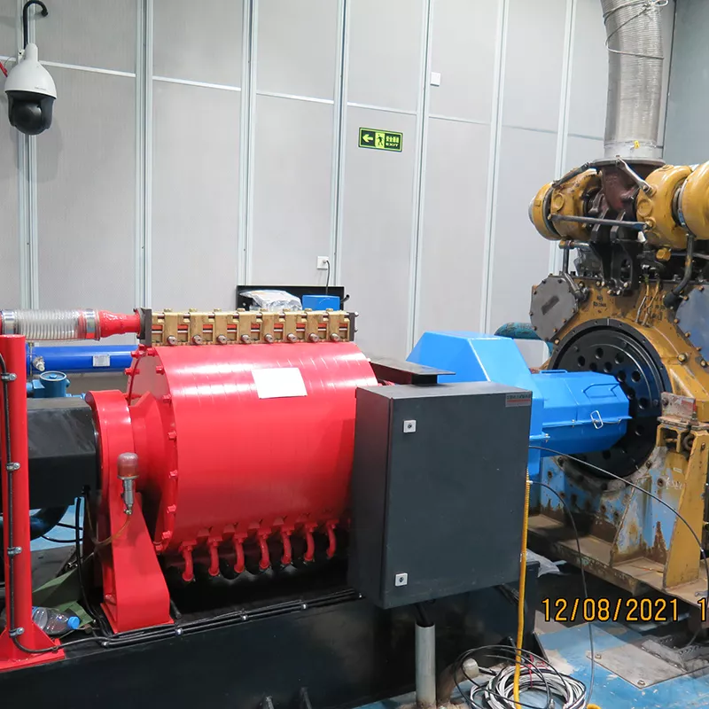
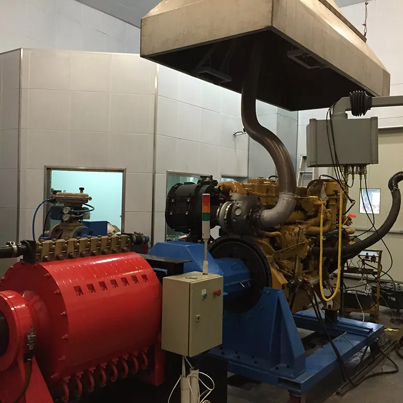
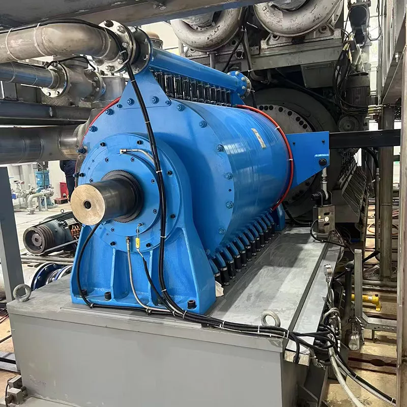
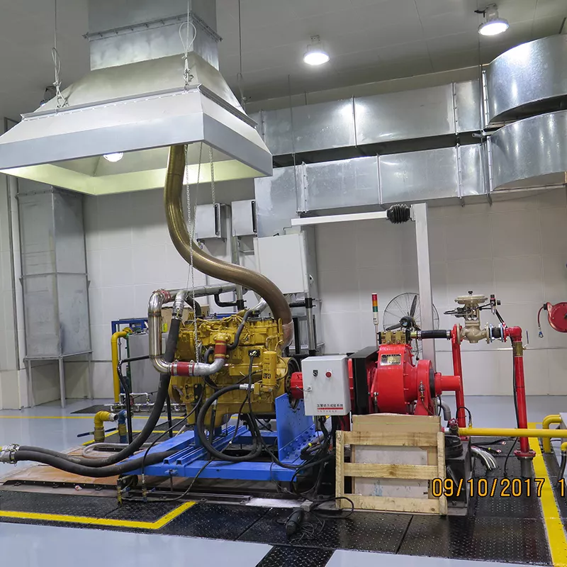
Hance hydraulic dynamometers deliver 35 kW to 10,000 kW of power absorption across the HDX and HDL series. The HDX platform accurately tests engines down to 5% of rated capacity, while the HDL series handles high-torque, low-speed diesel engines up to 10,000 HP. Matched couplings, fuel coolers and exhaust silencers complete a durable test-cell package.
The HDX series shares a common structural design and scales power absorption by adding stator and rotor assemblies. The HDL series extends into very high torque territory with a through-shaft design that accepts either-end drive or tandem dynamometers. Both series deliver low-inertia, high-absorption performance for continuous-duty engine power verification, quality assurance, endurance and certification testing.
High-power HDX dynamometers can precisely test low-power engines without switching to a smaller absorber, reducing the number of units required on the floor.
The HDX platform lets one structural design cover a wide power band by adding internal absorption elements, simplifying spares and service.
HDL dynamometers feature a through-shaft design that allows either end to be driven, accepts tandem dynamometers and supports accessory mounting including starting systems.
HDX and HDL series dynamometers operate in both clockwise and counter-clockwise directions with equal absorption capability, accommodating different engine orientations.
A hydraulic dynamometer converts engine output into heat through the interaction of water and rotating elements. Water flows through the inlet manifold, is accelerated outward by the rotor and decelerated in stator pockets. This continuous acceleration/deceleration creates the load. The absorbed power is measured from reaction torque on the trunnion-mounted stator housing, while cooling water removes the generated heat.
The engine crankshaft is coupled to the dynamometer rotor. Rotational energy enters the water brake through the drive shaft and coupling assembly.
Metered inlet manifolds direct water at the center of each rotor. Centrifugal force drives the water outward into stator pockets, where deceleration generates the absorption load.
The stator housing is mounted on trunnion bearings. The reaction torque it experiences is transmitted to a torque sensor with linkage and converted into horsepower. A speed sensor with gear assembly captures RPM.
Continuous water flow carries away the absorbed energy. Sufficient internal clearance eliminates the need for separate cooling water, and water flow requirement for loading is typically less than 6 GPM per 100 HP of applied load.
The HDX water-brake dynamometer features a trunnion-mounted, fixed-base design with cast iron rotors and stators. The dimensional drawing below shows the overall envelope (A), base footprint (B, C) and shaft centerline dimensions (D through J) for installation planning.
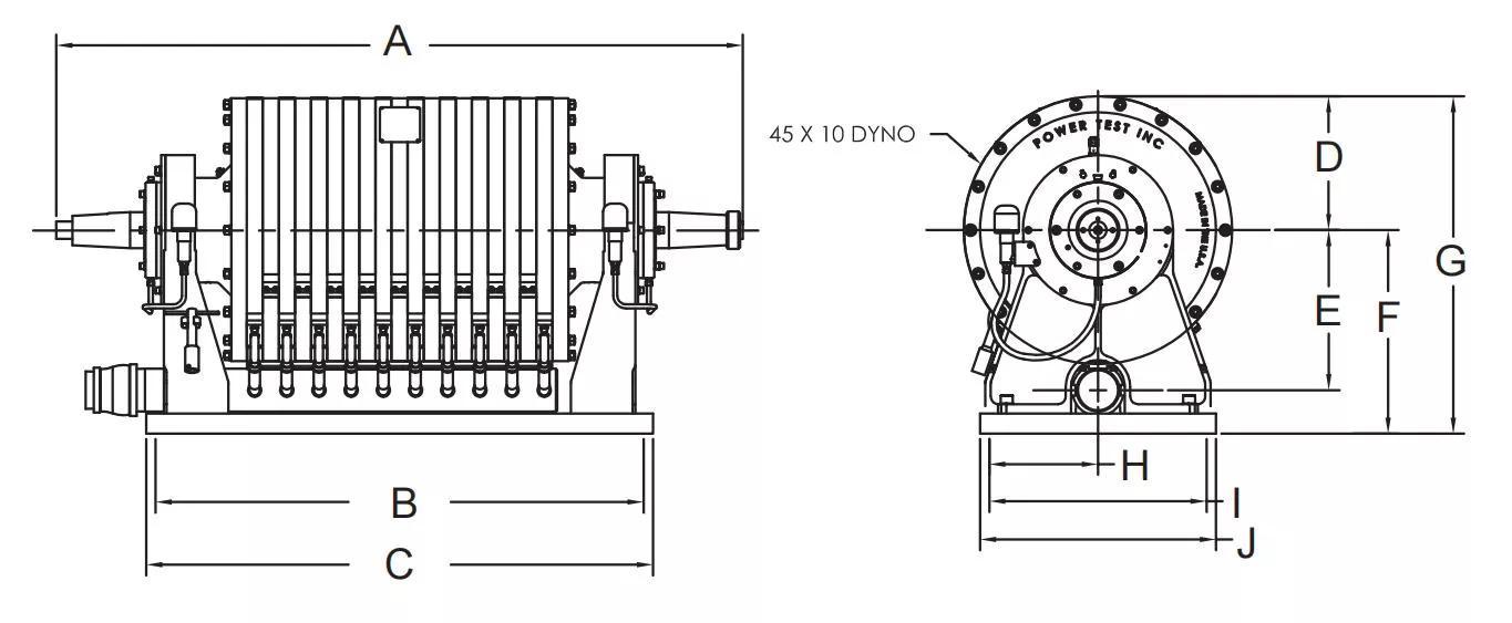
Refer to the dimensional table in the HDX power & torque curve document for complete A–J dimensions across HDX2000 through HDX4000 models. Other centerline heights available upon request.
The HDX series comprises 12 distinct models sharing a common structural design. Power absorption capacity is increased by adding stator and rotor assemblies. Designed for truck, off-highway, military and mining engine testing, HDX dynamometers operate in both clockwise and counter-clockwise directions.
| Model | Part # | Dimensions (inches) | Weight (lbs) | Inertia (lb-ft²) | ||
|---|---|---|---|---|---|---|
| A | B | C | ||||
| HDX2000 | 5232 1/2 | 35 1/4 | — | — | 2,690 | 195.4 |
| HDX2300 | 5535 1/2 | 38 1/4 | — | — | 2,960 | 227.8 |
| HDX2700 | 5838 1/2 | 41 1/4 | 12 1/2 | 15 | 3,230 | 260.1 |
| HDX3000 | 6141 1/4 | 44 1/4 | — | — | 3,500 | 292.4 |
| HDX4000 | 6444 1/4 | 47 1/4 | — | — | 3,770 | 324.7 |
| Model | Rated Power (HP) | Peak Torque (ft-lbs) | Peak Torque RPM |
|---|---|---|---|
| HDX2000 | 2,700 | 9,265 | 1,500 |
| HDX2300 | 3,150 | 10,809 | 1,500 |
| HDX2700 | 3,600 | 12,353 | 1,500 |
| HDX3000 | 4,050 | 13,897 | 1,500 |
| HDX4000 | 4,500 | 15,000 | 1,500 |
Power rises with engine speed and becomes constant from approximately 2,000 RPM through 4,000 RPM. Torque peaks around 1,200–1,500 RPM and decreases at higher speeds, consistent with constant-power absorption.
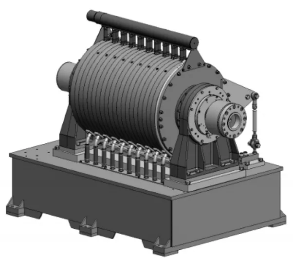
The HDL series is designed for testing high-torque, low-speed diesel engines in mining, marine, construction and power generation. Application power ranges through 8,000 HP (5,968 kW) at speeds up to 2,500 RPM and torque up to 45,000 lb-ft (61,011 Nm). These trunnion-mounted, fixed-base dynamometers feature a through-shaft design and fabricated steel sub-base.
| Model | Dimensions (inches) | Weight (lbs) | Inertia (lb-ft²) | ||
|---|---|---|---|---|---|
| A | B | C | |||
| HDL1200 | 56 1/4 | 49 | 43 1/4 | 8,750 | 411 |
| HDL2400 | 62 7/8 | 57 3/4 | 52 | 10,500 | 799 |
| HDL3600 | 69 1/2 | 66 1/2 | 60 3/4 | 12,250 | 1,187 |
| HDL4800 | 76 1/8 | 75 1/4 | 69 1/2 | 14,000 | 1,575 |
| HDL6000 | 84 3/4 | 84 | 78 1/4 | 15,750 | 1,963 |
| HDL10000 | 84 3/4 | 84 | 78 1/4 | 15,750 | 1,963 |
| Model | Rated Power | Peak Torque | Peak Torque RPM |
|---|---|---|---|
| HDL1200 | 1,600 HP (1,194 kW) | 9,337 lb-ft (12,664 Nm) | 900 |
| HDL2400 | 3,200 HP (2,387 kW) | 18,674 lb-ft (25,329 Nm) | 900 |
| HDL3600 | 4,800 HP (3,581 kW) | 28,011 lb-ft (37,993 Nm) | 900 |
| HDL4800 | 6,400 HP (4,774 kW) | 37,348 lb-ft (50,658 Nm) | 900 |
| HDL6000 | 8,000 HP (5,968 kW) | 46,684 lb-ft (63,322 Nm) | 900 |
| HDL10000 | 13,404 HP (10,000 kW) | 67,050 lb-ft (90,900 Nm) | 1,200 |
HDL6000 and HDL10000 share the same physical envelope but differ in absorption capacity. HDL10000 reaches its rated power at 1,400 RPM and maintains it through 2,500 RPM.
Accurate alignment between the engine and dynamometer is critical for vibration control and test repeatability. Hance supplies SAE-matched coupling assemblies that bolt directly to common engine flywheel patterns. HDL models include a 315 series drive shaft companion flange as standard.
| Model | Technical Specifications | Application | Remark |
|---|---|---|---|
| 52501 | SAE1 flywheel adapter | QST30, QSK23, QSK50 | |
| 52502 | SAE2 flywheel adapter | — | |
| 52503 | SAE3 flywheel adapter | — | |
| 52504 | SAE4 flywheel adapter | — | |
| 52505 | SAE5 flywheel adapter | Cat 3512, 3516 |
Coupling assemblies include the flywheel adapter plate and drive coupler. Proper pilot engagement ensures concentric alignment without trial-and-error shimming. Confirm your engine flywheel housing SAE size before ordering.
During dynamometer testing, returning diesel fuel carries heat from the injection system. A dedicated return cooler stabilises fuel temperature, protects the fuel system and helps maintain consistent combustion conditions across the test cycle.
| Model | Technical Specifications | Application | Remark |
|---|---|---|---|
| 786500 | Diameter 3/4 inch, cooling area 3 m² | QST30, QSK23 | |
| 786501 | Diameter 1 inch, cooling area 5 m² | QSK50, QSK60 | |
| 786502 | Diameter 1.5 inch, cooling area 8 m² | QSK78, QSK95 |
Cooler selection should account for fuel flow rate, return fuel temperature and the available cooling-water temperature.
Engine test cells require controlled exhaust routing for operator safety, acoustic comfort and consistent back-pressure. Hance mufflers are sized by inlet diameter and provide approximately 25 dB of noise reduction across the QSK and Cat engine range.
| Model | Technical Specifications | Application | Remark |
|---|---|---|---|
| 4350.00 | Diameter 150 mm, noise reduction 25 dB | QSK19/23, QST30 | |
| 4351.00 | Diameter 250 mm, noise reduction 25 dB | QSK50, QSK60 | |
| 4352.00 | Diameter 300 mm, noise reduction 25 dB | QSK78, Cat 3516 | |
| 4353.00 | Diameter 350 mm, noise reduction 25 dB | QSK95, Cat 3516C | |
| 4354.00 | Diameter 400 mm, noise reduction 25 dB | 16PA6 | |
| 4354.00 | Diameter 450 mm, noise reduction 25 dB | 16PA6 |
Muffler inlet diameter should match or exceed the engine exhaust outlet. For test cells with stringent acoustic requirements, additional attenuation may be required.
Power rating alone does not define a complete test-cell system. These factors determine the dynamometer series, coupling arrangement, fuel cooling capacity and exhaust hardware.
Peak power, peak torque and the shape of the torque curve determine the minimum absorber capacity and low-speed absorption requirement.
The SAE flywheel housing size dictates which coupling adapter is required. QST and QSK families have established Hance adapter references.
Continuous endurance testing demands more cooling capacity and water retention than short performance pulls. Duty cycle affects cooler and recirculation sizing.
Once-through or recirculated cooling, inlet temperature and allowable temperature rise determine the required flow rate and heat-rejection method.
Cell layout, stack height and local noise regulations influence muffler selection and whether secondary silencing is needed.
Return fuel flow and temperature, tank location and fuel conditioning requirements determine fuel cooler model and placement.
Hance hydraulic dynamometers and auxiliary equipment are used across engine manufacturing, remanufacturing, research and field service operations in mining, marine, construction, power generation and propulsion industries.
Heavy-duty diesel engine remanufacturing
Truck, off-highway and mining engine testing
Military engine overhaul and acceptance testing
Multi-variety production test lines
Marine and power-generation engine testing
Engine repair shops with mixed engine fleets
Practical answers for selecting a hydraulic dynamometer and planning the supporting test-cell systems.
Hydraulic (water-brake) dynamometers typically offer higher power density, lower inertia and greater tolerance for high-torque, low-speed operation. They are well suited to large diesel engines and applications where a compact absorber is needed.
Yes. The HDX series can accurately test engines down to approximately 5% of its rated capacity. That wide turndown allows a single dynamometer to cover a mixed engine population without switching to a smaller absorber.
Choose HDX for medium-to-high power diesel and gasoline engines from 35 kW to 3,300 kW, especially where mixed engine populations require wide turndown. Choose HDL for high-torque, low-speed diesel engines up to 10,000 HP (7,457 kW) and 50,000 lb-ft (67,820 Nm), typical of mining, marine and power generation applications.
Identify the engine flywheel housing SAE size. Hance coupling models are referenced to SAE1 through SAE5, with specific recommendations for QST30, QSK23, QSK50, Cat 3512 and Cat 3516 engines. Confirm the flywheel housing size before ordering.
It depends on the fuel system and test duration. Long-duration tests and engines with high return-fuel flow benefit from active cooling to keep fuel temperature stable. The cooler also protects fuel system components from heat-related wear.
The standard Hance muffler range provides approximately 25 dB of attenuation. If the test cell has stricter acoustic limits, additional silencing or acoustic treatment may be required.
Water flow depends on the absorbed power and allowable temperature rise. As a reference, large dynamometer cooling systems are often sized in the range of 3.5 GPM per 100 HP (approximately 19 L/min per 100 kW). Hance provides the specific flow requirement for each model.
Explore compatible Hance systems for cooling-water recirculation, engine cooling control and test-cell data acquisition.
Share your engine model, flywheel housing, power rating and test-cell conditions with Hance for model selection, coupling confirmation and accessory sizing.