

Inquiry
Form loading...
hospital floor.jpg
Loading...
Loading...
Loading...
hospital floor.jpg
Loading...
Loading...
Loading...
hospital floor.jpg
Loading...
Loading...
Loading...
hospital floor.jpg
Loading...
Loading...
Loading...
hospital floor.jpg
Loading...
Loading...
Loading...
hospital floor.jpg
Loading...
Loading...
Loading...
hospital floor.jpg
Loading...
Loading...
Loading...
hospital floor.jpg
Loading...
Loading...
Loading...
hospital floor.jpg
Loading...
Loading...
Loading...

Engine trolley

Available in three types: light, medium, and heavy, with load capacities of 1 ton, 4 tons, and 8 tons respectively.

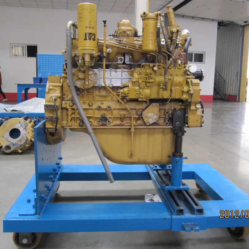
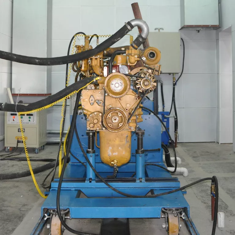
    Engine trolley supporting a heavy-duty diesel engine in an Hance dynamometer test cell
    Engine Test Support Equipment

    Engine Test Trolley

    A movable engine mounting platform that holds the engine at the correct centerline height for dynamometer testing. Three load classes cover 1, 4 and 8 ton engines, and the front end connects directly to standard SAE flywheel housings.

    1 / 4 / 8 tLight, medium, heavy
    750–900 mmCenter height
    SAE 0#–6#Flywheel housing fit
    Three load classes

    A trolley size for every engine family

    The range is divided into light, medium and heavy types. Each type pairs a rated load capacity with its own center height, so the engine crankshaft axis can be aligned with the dynamometer before the test cell is closed up.

    Engine trolley capacity and center height                Data as supplied by Hance Dyno
    TypeLoad capacityCenter heightTypical engine class
    Light duty1 ton750 mmCompact and light automotive or industrial engines
    Medium duty4 tons870 mmMid-size diesel engines for vehicle and industrial use
    Heavy duty8 tons900 mmLarge heavy-duty and high-displacement diesel engines

    Load capacity refers to the engine mass the trolley is designed to carry. Confirm the actual engine mass, center of gravity and accessory load when selecting the trolley type.

    Engine interface

    Front mounting through the flywheel housing

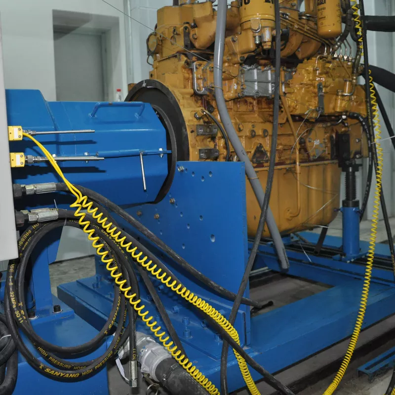
    Instead of clamping the engine by its sump or block sides, the trolley bolts to the engine flywheel housing. This is the same interface the dynamometer uses, so the engine keeps the alignment it will have during the test.

    Engine trolley front plate bolted to a diesel engine flywheel housing

    Front support features

    • Bolts directly to the engine flywheel housing

    • Compatible with all standard flywheel housings from SAE 0# to SAE 6#

    • Maintains the engine centerline height relative to the dynamometer

    • Allows the engine to be prepared and aligned away from the test bed

    Adjustment and mobility

    Three-dimensional rear adjustment for different engine sizes

    The rear end of the trolley can be adjusted in three dimensions according to the engine size. That is what allows one trolley to accept different engine lengths, block profiles and mounting foot positions without a dedicated fixture for every model.

    What the adjustment covers

    • Longitudinal position to suit different engine lengths

    • Lateral position to suit different mounting foot spacing

    • Vertical height to suit different block and sump profiles

    • Rear support points that stabilize the engine during run-in

    • Rapid installation and positioning of imported and domestic engines

    Adjustable rear supports and casters on an engine test trolley
    Working principle

    From bare engine to a coupled test

    The trolley is a preparation and transport platform as much as a test fixture. Mounting the engine on it before the test cell is occupied keeps the dynamometer free for the next job.

    01Mount the engine

    The flywheel housing is bolted to the trolley front support using the matching housing interface.
    02Set the center height

    The light, medium or heavy trolley places the engine at its designed centerline height of 750, 870 or 900 mm.

    03Adjust the rear supports

    The rear end is set in three dimensions so the engine sits level and stable on its own mounting points.

    04Move in and couple

    The trolley is wheeled into the test cell and the engine is coupled to the dynamometer for the test run.

    Selection inputs

    Information needed to specify a trolley

    Trolley selection is driven by the engine itself and by the test cell layout. Both sets of inputs should be confirmed before the order is placed.

    Engine mass and distributionTotal engine mass including accessories, plus the approximate center of gravity position.
    Flywheel housing standardThe SAE housing size used by the engine, so the correct front interface is supplied.
    Engine dimensionsOverall length, block and sump profile, and mounting foot spacing for the rear supports.
    Dynamometer centerlineThe center height of the dynamometer the engine will be coupled to.
    Test cell handlingHow the trolley is moved and positioned, and whether floor rails, level pads or lifting points are used.
    Services routingSpace needed for fuel, coolant, oil, exhaust and instrumentation connections around the engine.
    Buyer questions

    Engine trolley FAQ

    Answers to the questions engineers ask most often when planning engine mounting for a dynamometer test cell.

    What is an engine trolley used for?

    It carries and supports an engine at the correct centerline height so the engine can be prepared, moved into the test cell and coupled to a dynamometer for testing.

    How do I choose between the 1, 4 and 8 ton trolleys?

    Start with the engine mass including accessories. The light-duty trolley is rated at 1 ton with a 750 mm center height, the medium-duty at 4 tons with 870 mm, and the heavy-duty at 8 tons with 900 mm. The dynamometer centerline and engine dimensions should also be checked.

    Which engines fit the front mounting?

    The front end connects to the engine flywheel housing and is compatible with all standard flywheel housings from SAE 0# to SAE 6#.

    How does the trolley handle different engine sizes?

    The rear end of the trolley can be adjusted in three dimensions according to the engine size, which accommodates the rapid installation and positioning of imported and domestic engines.

    Can the engine be prepared away from the test bed?

    Yes. Mounting on a movable trolley allows the engine and its connections to be assembled outside the test cell and then rolled in for coupling, which keeps the dynamometer available for other work.

    What should be confirmed before ordering?

    Engine mass and center of gravity, flywheel housing standard, overall engine and mounting dimensions, the dynamometer centerline height, and how the trolley will be moved and secured in the cell.

    Complete the test cell

    Related Hance systems

    The trolley is normally specified together with the dynamometer, the control system and the engine support equipment around it.

    Specify the right engine trolley for your test cell

    Share the engine mass, flywheel housing standard, engine dimensions and dynamometer centerline height with Hance, and we will confirm the trolley type and mounting arrangement.

    Request Engine Trolley Selection