Reduce operating water demand
Recovering and reusing cooling water reduces dependence on continuous once-through supply and helps control day-to-day operating cost.

 Home
About Us
Product
Home
About Us
Product
 Hydraulic dynamometer
Eddy current dynamometer
AC dynamometer
Engine cooling water column
Control and data acquisition system
Engine trolley
Recycling Water System
Hydraulic dynamometer
Eddy current dynamometer
AC dynamometer
Engine cooling water column
Control and data acquisition system
Engine trolley
Recycling Water System
 News
Contact Us
News
Contact Us
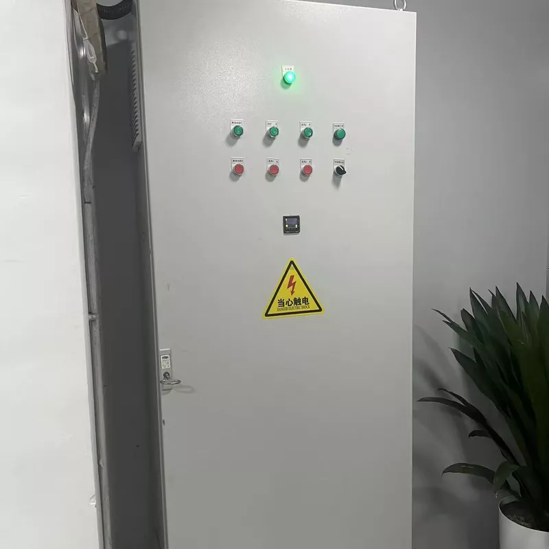
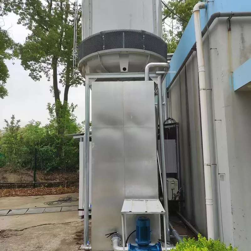
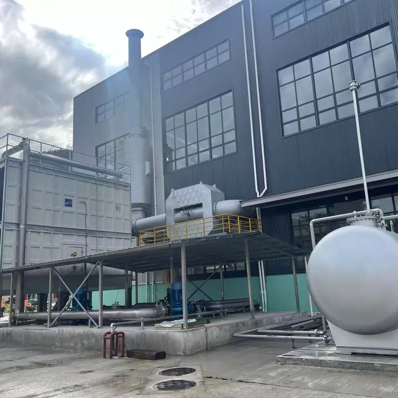
A purpose-sized cooling-water loop for water brake dynamometer test cells. It recovers and reuses process water while supporting the pressure, flow and heat-removal conditions required for dependable engine testing.
The Hance water recirculation system is designed for water brake dynamometers and can also work with other water-cooled heat sources. With sufficient system capacity, one installation can support several dynamometers or multiple heat loads.
Recovering and reusing cooling water reduces dependence on continuous once-through supply and helps control day-to-day operating cost.
A controlled water supply helps protect the dynamometer cooling circuit from inconsistent supply conditions and unwanted contamination.
Correct system sizing supports the water pressure, flow rate and heat rejection needed for stable dynamometer operation.
Recirculation and evaporative heat rejection reduce the volume of hot process water sent directly to drain.
The system forms a reusable cooling-water circuit around the dynamometer and its connected cooling equipment. Final arrangement and capacity are engineered for the test-cell heat load and site conditions.
Conditioned water is delivered to the water brake dynamometer and any connected water-cooled test-cell equipment.
During operation, the water absorbs heat generated by the dynamometer and other connected heat sources.
Warm return water passes through the selected cooling equipment so that accumulated test heat can be removed.
The cooled water is retained and returned to the supply loop, ready for the next stage of testing.
Choose the flow-rate range that matches the dynamometer and engine application. Final system selection should also consider simultaneous heat loads, inlet-water conditions and the complete test-cell arrangement.
| Model | Technical Specifications | Application | Remark |
|---|---|---|---|
| 60340.01 | Water flow rate: 60 tons/hour | QST30 QSK23 | |
| 60341.01 | Water flow rate: 80 tons/hour | QSK50 | |
| 60342.01 | Water flow rate: 100 tons/hour | QSK60 | |
| 60343.01 | Water flow rate: 120 tons/hour | QSK78 | |
| 60344.01 | Water flow rate: 140 tons/hour | QSK95 |
Application references are based on the supplied product data. Contact Hance with the dynamometer model, engine rating, test duration and site conditions for final confirmation.
Flow rate alone does not define a complete dynamometer cooling-water system. These inputs help establish the required capacity, circulation arrangement and cooling equipment.
Rated power, test cycle and operating duration determine how much heat the system must continuously remove.
The selected circulation system must deliver stable water conditions at the connected dynamometer and cooling circuits.
Entering-water temperature and allowable temperature rise affect cooling capacity and equipment selection.
Managing debris, scale, corrosion and biological growth supports cooling efficiency and equipment service life.
A multi-dynamometer facility must be sized for the intended simultaneous load, not simply the number of test cells.
Available space, climate, water availability and the chosen heat-rejection method influence the final arrangement.
The system can be engineered around a single water brake dynamometer or incorporated into a larger facility cooling network serving several compatible loads.
Water brake and hydraulic dynamometer test cells
Heavy-duty diesel engine testing
Single-cell or multi-dynamometer facilities
QST30 and QSK-series engine applications
Other compatible water-cooled heat sources
Sites with limited water supply or discharge capacity
Practical answers for planning a dynamometer cooling-water loop and preparing the information needed for system selection.
It is a reusable cooling-water circuit that supplies water to a dynamometer, collects the heated return water, removes excess heat and sends the cooled water back into the test-cell loop.
Recirculation retains process water, reducing continuous water demand and hot-water discharge. It also gives the facility greater control over water quality, flow and cooling conditions.
Yes. The supplied product information states that one system can serve several dynamometers or other heat sources when sufficient capacity is engineered into the installation.
Start with the listed engine application, then confirm the combined heat load, required water flow and pressure, inlet temperature, test duration, number of connected loads and site conditions.
Not necessarily. A recirculation loop must work with an appropriate method of rejecting heat from the return water. The final cooling arrangement depends on the test load, climate, available utilities and facility design.
Provide the dynamometer model, engine family and rated power, expected test duration, number of simultaneous test cells, target water conditions, available utilities and installation environment.
Explore compatible Hance systems for power absorption, engine cooling and test-cell measurement and control.
Share your dynamometer, engine application, flow demand and test-cell conditions with Hance for model selection and system planning.