

Inquiry
Form loading...
hospital floor.jpg
Loading...
Loading...
Loading...
hospital floor.jpg
Loading...
Loading...
Loading...
hospital floor.jpg
Loading...
Loading...
Loading...
hospital floor.jpg
Loading...
Loading...
Loading...
hospital floor.jpg
Loading...
Loading...
Loading...
hospital floor.jpg
Loading...
Loading...
Loading...
hospital floor.jpg
Loading...
Loading...
Loading...
hospital floor.jpg
Loading...
Loading...
Loading...
hospital floor.jpg
Loading...
Loading...
Loading...

Engine cooling water column

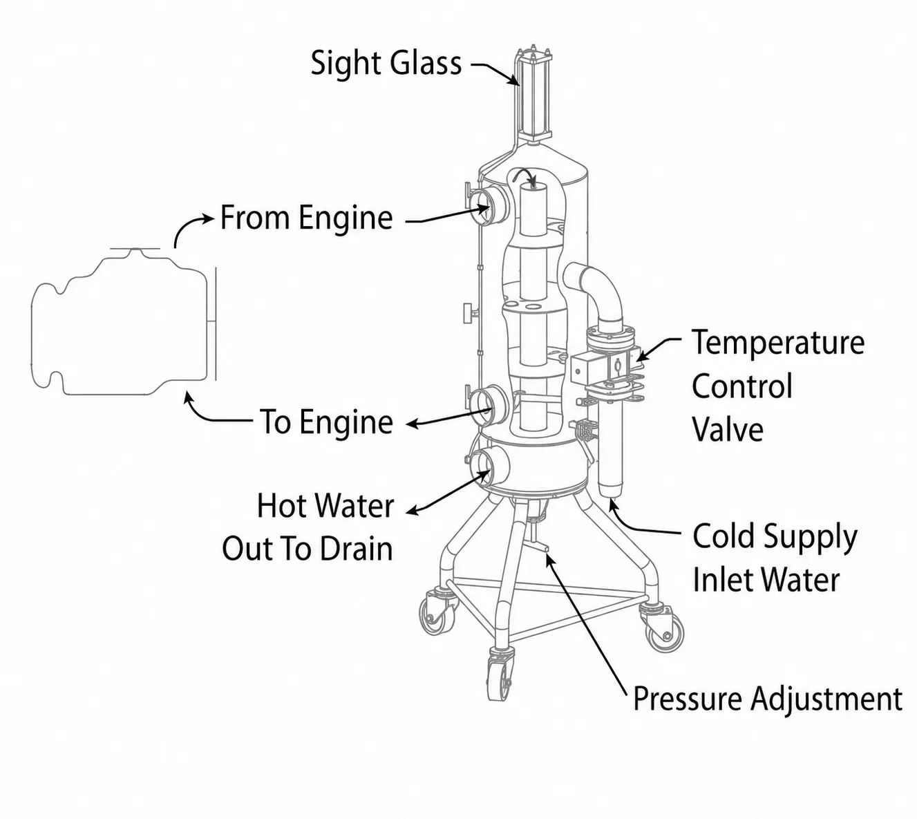
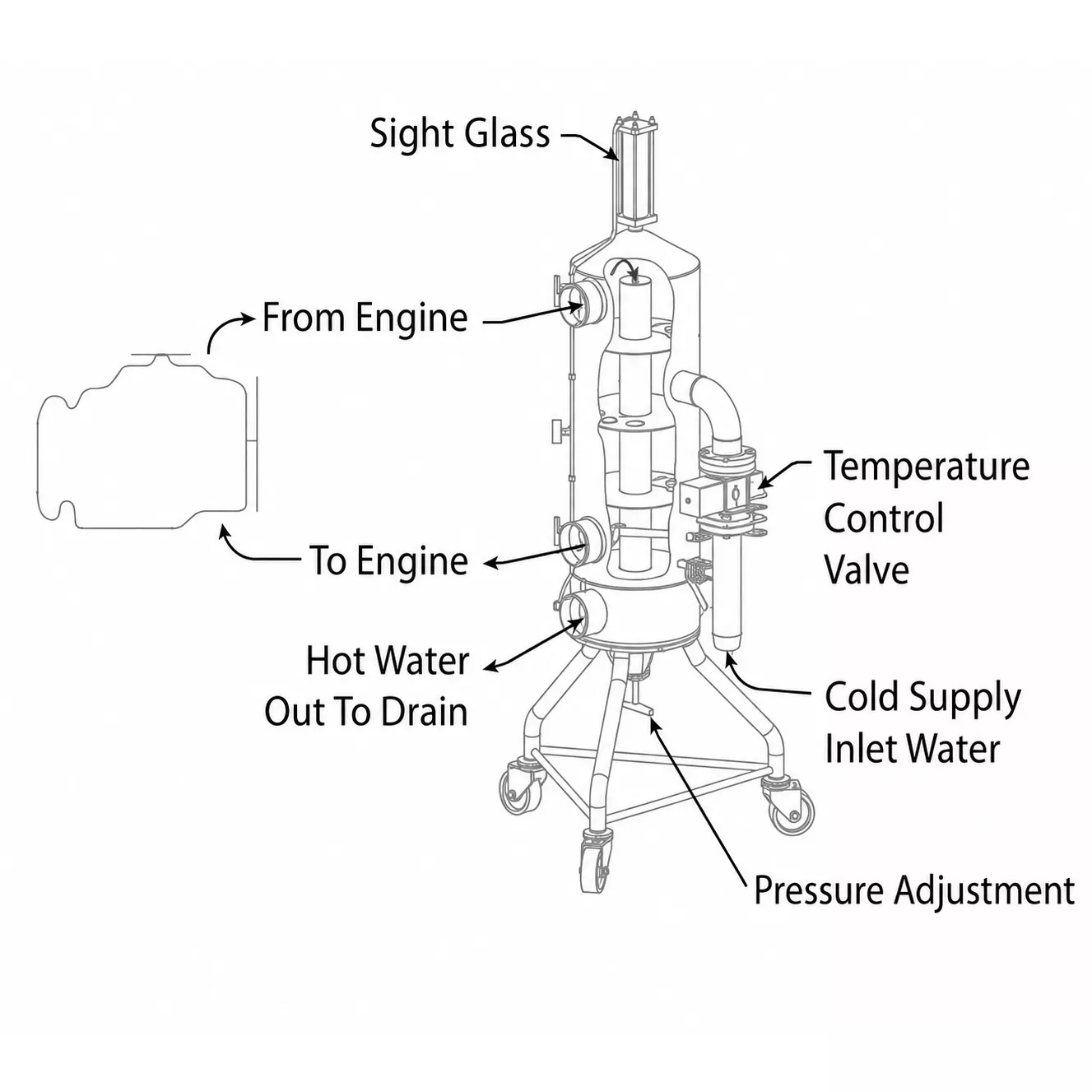
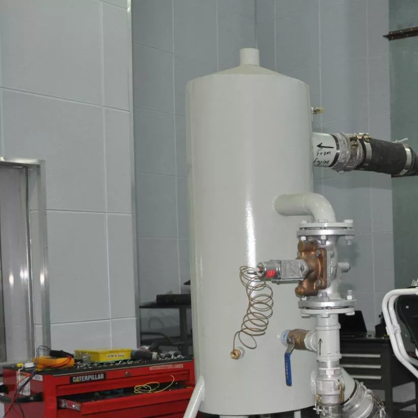
The Power Test Engine Cooling Column is a temperature-controlled, pressure-regulated recirculation tank that simulates the engine jacket water cooling system's operating characteristics, eliminating the need for a radiator and fan.

    Engine cooling water column
    Engine Test Support Equipment

    Engine Cooling Water Column

    Stable, visible and adjustable coolant control for engine testing. The system helps maintain the target coolant temperature while providing clear pressure, temperature and leak monitoring.

    160–230°F                    Adjustable range
    71–110°C                    Metric range
    15 psi                    Maximum pressure
    Portable / Wall                    Mounting options
    Designed for control

    Reliable cooling during every test

    The Engine Cooling Water Column is built to support repeatable engine tests with straightforward adjustment, at-a-glance monitoring and a stable, service-friendly platform.

    01                Stable coolant temperature

    Maintains the desired engine coolant temperature throughout the test cycle.
    02                Pressure-regulated adjustment

    An adjustable pressure-regulated system supports controlled test conditions.

    03                Visible leak detection

    An integrated sight glass makes coolant condition and potential leakage easier to observe.

    04                Clear analog monitoring

    Large analog temperature and pressure gauges provide fast, direct readings.

    05                Stable mobile platform

    Urethane casters and a low center of gravity support smooth movement and stable positioning.

    06                Flexible installation

    Available in portable and wall-mount configurations to suit different test-cell layouts.

    Performance data

    Water supply requirements

    Select the cooling-column capacity for the engine and test-cell demand. All listed models require a clean, clear inlet-water supply.

    Cooling Column Operating Requirements                Scroll horizontally on small screens
    DescriptionPart #Inlet Water RequirementsMinimum Flow RateMaximum Pressure
    Cooling Column – 1,000 HP23823Clean, clear water supply @ 60 psi (413 kPa) and less than 85°F (29°C)6 gpm (23 L/min) / 100 HP (75 kW)15 psi (103 kPa)
    Cooling Column – 1,400 HP63591.1Clean, clear water supply @ 60 psi (413 kPa) and less than 85°F (29°C)6 gpm (23 L/min) / 100 HP (75 kW)15 psi (103 kPa)
    Cooling Column – 2,100 HP63590.1Clean, clear water supply @ 60 psi (413 kPa) and less than 85°F (29°C)6 gpm (23 L/min) / 100 HP (75 kW)15 psi (103 kPa)
    Cooling Column – 3,150 HP63565.1Clean, clear water supply @ 60 psi (413 kPa) and less than 85°F (29°C)6 gpm (23 L/min) / 100 HP (75 kW)15 psi (103 kPa)
    Cooling Column – 4,500 HP63564.1Clean, clear water supply @ 60 psi (413 kPa) and less than 85°F (29°C)6 gpm (23 L/min) / 100 HP (75 kW)15 psi (103 kPa)
    Cooling Column – 5,000 HP63527.1Clean, clear water supply @ 60 psi (413 kPa) and less than 85°F (29°C)6 gpm (23 L/min) / 100 HP (75 kW)15 psi (103 kPa)
    Additional selection range

    Technical specifications

    The following inlet sizes and engine-displacement ranges are taken from the supplied Cooling Water Column Technical Specifications table.

    Cooling Water Column Technical Specifications                Extracted from the supplied Word table
    ModelTechnical SpecificationsApplicationRemark
    60340Inlet diameter: 1 inch3–19 Liter Engines
    60341Inlet diameter: 2 inch19–60 Liter Engines
    60342Inlet diameter: 3 inch60–95 Liter Engines
    60343Inlet diameter: 3.5 inch95–110 Liter Engines
    Installation planning

    Dimensions & connections

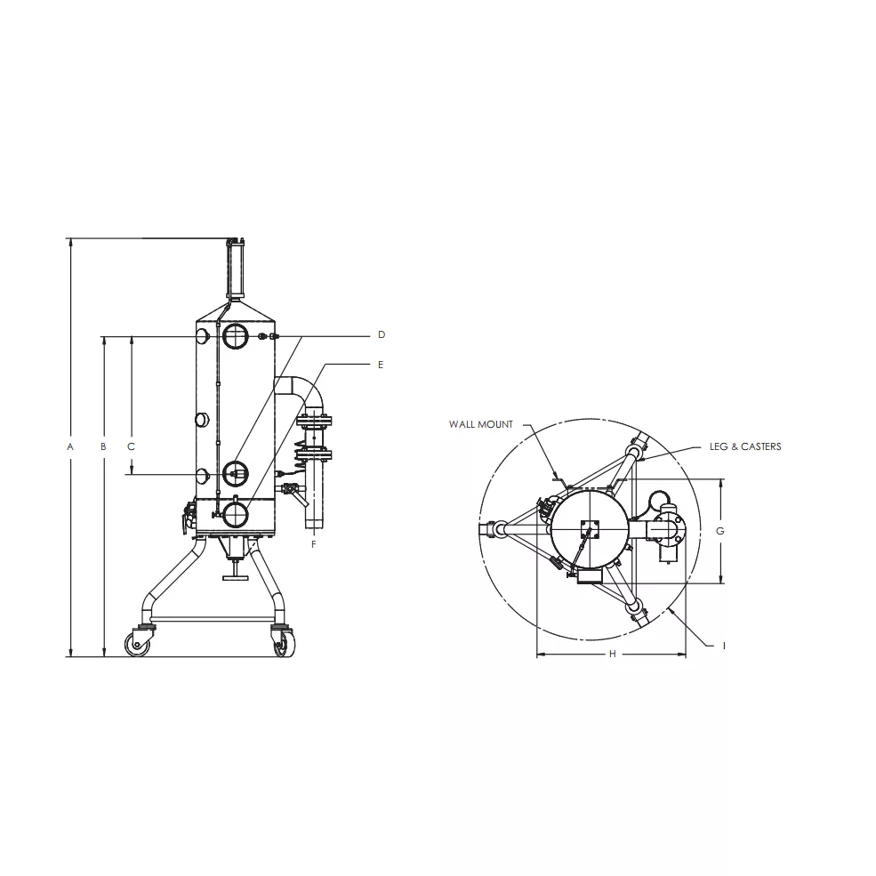
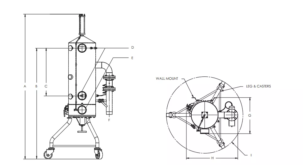
    Use the drawing references A–I with the matching table below. Both imperial and metric data are included for easier test-cell planning.

    Engine cooling water column dimensional drawing
    Dimensions (inches)                    Scroll horizontally on small screens
    DescriptionPart #ABCD (OD)E (NPT)F (NPT)GHI (Ø)Empty Weight (lbs)
    Cooling Column – 1,000 HP238238565 1/2284312132532
    Cooling Column – 1,400 HP635918565 1/228541 1/22129 3/845340
    Cooling Column – 2,100 HP635908565 1/2285422129 3/445350
    Cooling Column – 3,150 HP635658565 1/2285422129 3/445350
    Cooling Column – 4,500 HP635648565 1/2285432130 1/445365
    Cooling Column – 5,000 HP635279774 1/4367 3/8632130 1/445425
    Dimensions (mm)                    Scroll horizontally on small screens
    DescriptionPart #ABCD (OD)E (NPT)F (NPT)GHI (Ø)Empty Weight (kg)
    Cooling Column – 746 kW2382321591664711102762551330635813
    Cooling Column – 1044 kW6359121591664711127102385347461143155
    Cooling Column – 1566 kW6359021591664711127102515347461143159
    Cooling Column – 2349 kW6356521591664711127102515347461143159
    Cooling Column – 3356 kW6356421591664711127102765347681143166
    Cooling Column – 3729 kW63527971886914187152765347681143193

    NPT = National Pipe Thread. OD = outside diameter. Dimensional letters correspond to the supplied drawing.