Dynamometer operation
Dyn Pro gives the operator control over the connected dynamometer functions from a clear point-and-click interface.

 Home
About Us
Product
Home
About Us
Product
 Hydraulic dynamometer
Eddy current dynamometer
AC dynamometer
Engine cooling water column
Control and data acquisition system
Engine trolley
Recycling Water System
Hydraulic dynamometer
Eddy current dynamometer
AC dynamometer
Engine cooling water column
Control and data acquisition system
Engine trolley
Recycling Water System
 News
Contact Us
News
Contact Us
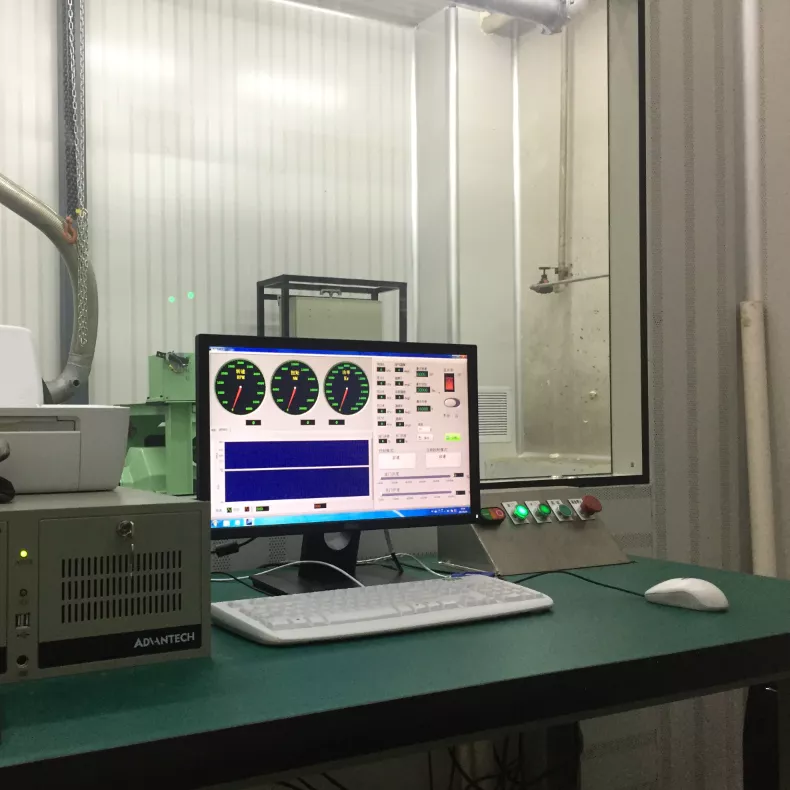
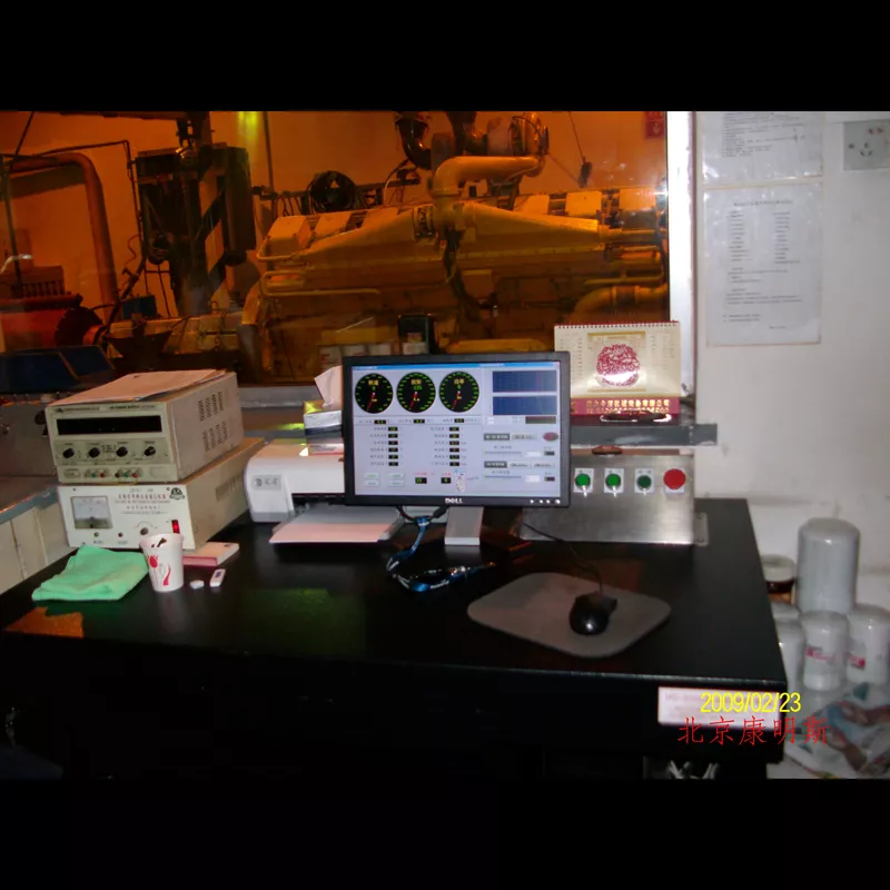
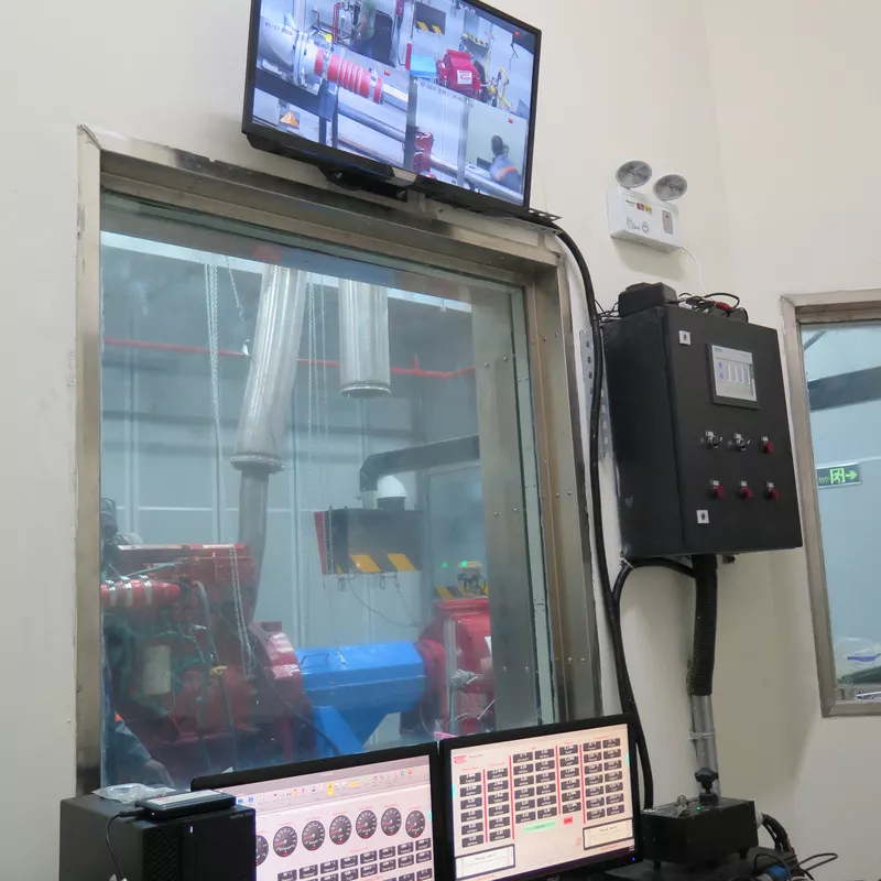
The control core of a Hance dynamometer test cell, combining Dyn Pro operator control, test-result acquisition, peripheral instrumentation and industrial cabinet integration.
HD-3000 and Dyn Pro bring dynamometer operation and supporting measurement channels into a unified Windows-based environment. Operators can control test functions while viewing the measurements needed to understand engine and system performance.
Dyn Pro gives the operator control over the connected dynamometer functions from a clear point-and-click interface.
HD-3000 acquires results from the dynamometer, engine instrumentation and configured peripheral equipment.
Connect smoke, emissions, pressure, temperature, ECM and fuel-measurement functions within the test system.
Fan filtration, power management and surge-voltage protection support installation in test or control rooms.
The HD-3000 architecture links measurement accessories and engine interfaces to the operator workstation so the test can be controlled and evaluated from one environment.
Configured sensors and accessories provide dynamometer, engine, emissions, pressure, temperature and fuel data.
HD-3000 receives measurement data through the system's configured channels and interfaces.
Dyn Pro presents operating information and gives the user point-and-click access to test functions.
The integrated environment gives operators the data needed to assess the completed or active test.
The supplied HD-3000 product information identifies a range of accessories and engine interfaces that can contribute measurements to the complete dynamometer test.
Smoke meter for diesel smoke measurement
Emissions analyzer for exhaust-gas test data
Engine instrumentation unit with pressure channels
Engine instrumentation unit with temperature channels
Heavy-duty diesel engine ECM interface channel
Fuel measurement unit integration
The HD-3000 is PC based, but the supporting cabinet is engineered as industrial test equipment rather than ordinary office hardware.
Hance systems can place the operator interface where the facility workflow requires it, while maintaining visual access to the engine, dynamometer and supporting equipment.
The final HD-3000 configuration should reflect the dynamometer type, engine electronics, supporting instruments and the test procedure used by the facility.
Practical answers for planning a new dynamometer control system or configuring a complete Hance test cell.
HD-3000 is the core control and data-acquisition platform for Hance dynamometer instrumentation. It controls the test system and acquires results from the configured measurement equipment.
Dyn Pro is the operator environment that provides access to dynamometer functions and presents the acquired test information.
The supplied product information lists a smoke meter, emissions analyzer, engine pressure and temperature instrumentation, a heavy-duty diesel ECM channel and a fuel measurement unit.
The cabinet is designed for flexible placement in either the harsher dynamometer test room or the operator's control room.
Provide the dynamometer type, desired control modes, sensor and channel list, engine interface, peripheral instruments, test procedure and installation environment.
Use HD-3000 with the dynamometer technology and facility-support systems appropriate to the engine test program.
Share the dynamometer, channel list, engine interface, accessories and installation requirements with Hance.