
 Home
 Hydraulic dynamometer

Engine testing / repeatable workflow
A repeatable engine dyno testing procedure begins before the engine starts. Define the test and acceptance criteria, verify the mounting and measurement setup, establish the required operating conditions, execute the approved load schedule, and retain enough context to explain the result. Repeatability depends on controlled conditions and traceable records, not simply on repeating a run.
This guide organizes the workflow for qualified test teams. It is not permission to operate equipment or a replacement for the engine, dynamometer and facility instructions. Engine limits, alignment tolerances, fastening requirements, protective functions and emergency actions must come from the approved equipment documentation and site procedures.
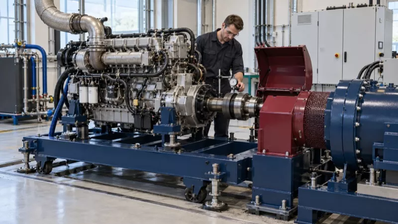
01 / ENGINE TESTING GUIDEPre-test information and test plan
Step 1: Define what the test must establish
Write the test objective before preparing the engine. A development map, repaired-engine acceptance check and production audit may require different operating points, durations and recorded variables. Identify the decision to be made and the evidence needed to support it.
Define the measurement boundary and engine configuration. List the fitted accessories, fuel specification, engine software or calibration, intake and exhaust arrangement, and relevant cooling conditions. For the underlying shaft-output boundary, see what an engine dynamometer measures.
If the intended decision concerns a complete installed vehicle, confirm that an isolated engine test is appropriate. Our engine dyno vs chassis dyno comparison distinguishes those questions. Choosing the wrong boundary cannot be corrected later by adding more report fields.
Step 2: Freeze the schedule and acceptance basis
Specify the required actual speed and torque points, test sequence, stabilization criteria and recording windows. Identify the permitted operating envelope and the source of the limits. A general article cannot supply universal safe temperatures, load ramps or engine-speed limits.
Decide what constitutes a complete run, what triggers a normal stop or a protective response, and how an aborted test will be recorded. Those actions need approval through the facility's procedures. Do not let an operator improvise a missing acceptance rule after seeing the result.
| Planning item | Record before setup | Readiness question |
|---|---|---|
| Engine identity | Model, identifier and configuration | Is this the engine and build covered by the test plan? |
| Test purpose | Required decision and acceptance document | Can the scheduled measurements support that decision? |
| Load schedule | Points, transitions, duration and direction | Is the complete cycle within approved equipment limits? |
| Measurements | Channels, locations, units and processing | Are the required instruments and interfaces available? |
| Operating conditions | Fuel, coolant, air and exhaust arrangement | Can the facility establish the specified conditions? |
| Stops and anomalies | Approved responses and recording method | Does the authorized team know how to handle deviations? |
Assign a run identifier and retain the configuration version. If a setting changes later, document the change and its effect on comparability. A result labeled only with the engine model is not enough to reconstruct the test.
02 / ENGINE TESTING GUIDEMounting, coupling and alignment
Step 3: Verify the support arrangement
Check the engine mass, accessories, center of gravity and mounting interfaces against the approved fixture arrangement. Inspect the equipment using the required procedure before installation. Preparation and movement require the site's authorized handling plan, personnel and equipment.
The Hance engine test trolley provides a movable mounting platform and adjustable rear support. Selection should reflect the engine and dynamometer geometry. The trolley's mounting interface is not a substitute for checking the support, securing method and shaft alignment in the final test position.
Record the installed adapters and support arrangement. This is particularly useful when a facility changes engine families: a fixture that fits one engine does not automatically establish the correct setup for the next. Keep the approved arrangement identifiable rather than relying on an operator's memory.
Step 4: Verify coupling installation and alignment
Use the coupling and equipment suppliers' approved method to establish the shaft relationship and check alignment. Record the measurement method, results and applicable acceptance criteria. Do not copy a generic alignment tolerance or fastening value from another installation.
Confirm the coupling's suitability for the approved speed, torque and engine application, including any design review required for torsional behavior. Appropriate personnel should resolve a mismatch before the test proceeds. Alignment is a measured condition, not an assumption based on two visually similar centerline heights.
Fit and verify the required guards through the approved readiness process. OSHA's machine-guarding overview describes the hazards of moving machinery. When inspection or adjustment requires access, use the site's authorized hazardous-energy controls; OSHA's hazardous-energy overview explains why unexpected energization is a concern.
These references identify general hazards, not the specific regulatory requirements for every facility. Never use this workflow to justify bypassing a guard or making adjustments near a rotating shaft.
03 / ENGINE TESTING GUIDESensor, fluid and safety checks
Step 5: Confirm the measurement chain
Verify that each required channel has the correct sensor, connection, name, location and unit. Review the calibration status and perform the approved installed checks. Confirm the torque reference and speed measurement arrangement according to the equipment instructions.
Check whether channels come from independent instruments or the engine controller. Label them accordingly. Verify the acquisition, timestamp and reporting configuration required by the test, particularly when calculated results combine channels with different response characteristics.
The Hance control and data acquisition system supports configured dynamometer, instrumentation and peripheral interfaces through HD-3000 and Dyn Pro. Confirm the project's actual channel list and instrument package. Do not assume that every display field, fuel instrument or protective function is standard equipment.
Step 6: Confirm fluid and facility readiness
Check the installed circuits against the approved diagrams and engine requirements. Engine coolant, dynamometer process water, fuel supply and return, and relevant auxiliary circuits have different functions. Verify the required readiness evidence for connections, fluid identity, supply conditions and leakage checks.
An engine cooling water column supports engine coolant conditions; a water recirculation system supports the process-water arrangement. Neither should be treated as proof that all thermal requirements have been met. Record the specified conditions at the relevant engine and equipment interfaces.
Confirm intake, exhaust, ventilation and any required sampling arrangements through the site procedure. A complete test-cell system checklist should identify those interfaces and their responsible owners before the engine reaches this stage.
Step 7: Complete the authorized readiness gate
The team should establish that required protective functions and emergency arrangements have been verified through approved methods. Do not improvise a fault simulation or assume that a healthy operator-screen value proves the safety system has been checked.
Record who released the installation for testing and whether any unresolved item prevents the scheduled run. A readiness checklist must allow an item to remain not ready; it is not simply a form completed to keep the schedule moving.
Useful records at this gate include:
The approved mechanical setup and alignment verification.
Instrument identification, calibration status and channel checks.
Verified fluid, intake, exhaust and utility arrangements.
Required protective-function verification and authorized release.
Any deviation, its disposition and the resulting test restrictions.
04 / ENGINE TESTING GUIDEWarm-up, load steps and shutdown
Step 8: Establish the specified initial conditions
Start and warm the engine only through the authorized procedure. Use the engine and facility documents for the sequence and limits. A fixed warm-up time taken from another engine does not prove that your required coolant, oil or other initial conditions have been reached.
For tests requiring stabilized conditions, define how stabilization is demonstrated and record the relevant measurements. HORIBA's engine-testing technical article explains the importance of thermal stability when collecting operating-point data. A transient test instead requires its specified initial state and time history; it should not be forced into a steady-state interpretation.
Avoid interpreting the earliest available data as an accepted test point simply because the speed display is close to the target. Relevant thermal and fluid conditions can still be changing. Use the agreed readiness criteria, not a visual impression of a smooth trace.
Step 9: Run the approved load schedule
Execute the documented sequence within the approved engine and dynamometer envelope. Record actual speed and torque, not only demands. Preserve the measurement window associated with each accepted point, along with relevant temperatures, pressures and events.
For a stabilized-point test, assess the required conditions before accepting the recording interval. For a sweep or transient profile, preserve the commanded and actual time histories and the defined processing method. Those test types are not interchangeable: different sequences may yield different contexts for the same displayed speed.
The load machine must suit the cycle. A hydraulic dynamometer is an absorbing system; a test requiring the dynamometer to drive the engine needs an appropriately configured motoring-capable system. Never add a motoring stage to a procedure merely because the software can display a corresponding setpoint.
If a required condition is not maintained, use the approved response and record the event. Do not continue solely to obtain a peak number or conceal a missing point with interpolation. The report should distinguish completed, interrupted and excluded intervals.
Step 10: Stop and leave the system in its approved state
Normal shutdown and emergency response are separate procedures. Use the engine and facility instructions for load removal, stopping, cooling and the required post-run state. This guide does not prescribe the order because equipment and hazard-control arrangements differ.
Retain the final events and any abnormal observations before closing the run record. Post-run inspection or maintenance must follow the authorized isolation and access procedure. Stopping the engine does not, by itself, establish that all electrical, hydraulic, thermal or mechanical energy is safe for access.
05 / ENGINE TESTING GUIDEData review and repeatability checks
Step 11: Validate the result before comparing it
Check completeness against the test plan. Confirm that the required operating points, channels and conditions are present and that the accepted intervals were identified correctly. Missing data should be recorded as missing, not converted into a pass by assumption.
Review torque-speed-power consistency, channel units, timing and the calculation basis of any fuel-consumption result. Investigate discontinuities and drift using raw data and event records. An engine dyno test report review connects these checks to the final acceptance decision.
Power Test's WinDyn5i documentation illustrates why test templates, sensor calibration and configuration are part of the recorded context. For your own system, confirm which functions are configured and preserve the evidence needed to reproduce the reported calculation.
Step 12: Repeat for a defined purpose
Define the repeat strategy before testing. The appropriate number of runs depends on the objective, expected variation, measurement capability and acceptance requirements. There is no universal repeat count that establishes validity for every engine program.
Compare matched operating points and conditions. Keep engine configuration, fuel, instrumentation, processing and relevant initial conditions consistent. If those change, annotate the comparison rather than attributing the difference immediately to the engine.
| Review gate | Evidence to retain | What prevents an unsupported conclusion |
|---|---|---|
| Test completion | Scheduled and actual points with accepted windows | Missing or interrupted points remain identifiable |
| Measurement validity | Channel checks, calibration and raw data | A repeated sensor error is not mistaken for accuracy |
| Comparable conditions | Configuration, fuel and thermal records | Changed conditions are not treated as engine improvement |
| Processing consistency | Timing, filters and calculation methods | Different processing is not hidden by similar graphs |
| Acceptance decision | Applicable specification and disposition | The decision follows evidence rather than a peak value |
Repeatability is not the same as accuracy. A repeated configuration or calibration error can produce consistent results. Where the program requires an uncertainty assessment, include the measurement chain and method rather than relying only on the spread between runs.
Close the loop with an auditable report
Retain engine identity, setup version, test schedule, instrument references, actual results, conditions, events and the acceptance basis. Explain deviations and identify any follow-up needed. Another authorized reviewer should be able to establish why a point was accepted without recreating the operator's memory of the test.
Share your engine configuration, test cycle and required report fields with Hance to discuss the mounting, load and measurement systems needed for the workflow.
Discuss your engine-test workflow.
Questions and answers
How should an engine be aligned to a dynamometer?
Use the approved coupling and equipment documentation, the specified measurement method and the relevant acceptance criteria. Record the installed result. A matching trolley height or flywheel interface is not a substitute for final alignment verification.
What must be checked before applying load?
The authorized readiness process should cover mechanical installation, instrumentation, fluids, intake and exhaust, utilities, required protective functions and the approved test limits. Resolve any item that prevents the intended run before proceeding.
How long should engine warm-up take?
Follow the engine-specific procedure and the test's initial-condition requirements. Time alone is not a universal readiness criterion. Record the required thermal and other conditions rather than importing a fixed duration from another setup.
How many repeat runs are needed?
Use the agreed test plan. The number depends on the required decision and statistical or measurement needs. Preserve equivalent conditions, and do not assume that repeated results prove the absence of calibration error.
Can a software test profile replace a written procedure?
No. The profile can define part of the configured sequence, but it does not by itself establish mounting readiness, authorized personnel, protective measures, exception handling or acceptance requirements. Those remain part of the approved test system and procedures.
Technical references
HORIBA — Engine Testing, Readout No. 13, February 2010: engine-test measurement and stabilized conditions.
Power Test — WinDyn5i: configuration and test-record context.
OSHA — Machine Guarding and Control of Hazardous Energy: general hazard references, not site-specific operating instructions.
This framework is for planning and reviewing qualified testing work. It does not replace manufacturer instructions, the approved risk assessment, local requirements or the site's operating and emergency procedures.