
 Home
 Hydraulic dynamometer

Water brake testing / working principle
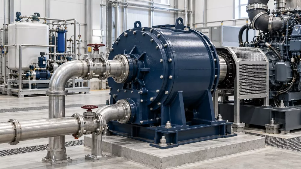
A hydraulic dynamometer of the water-brake type absorbs engine shaft power by moving water between a rotating rotor and a restrained stator. The resulting fluid forces resist shaft rotation. Torque and rotational speed are measured to calculate power, while the absorbed energy becomes heat that the water circuit must carry away.
That explanation contains three separate jobs: creating a controlled load, measuring the engine's output, and removing test heat. Understanding their relationship helps you specify a complete test system and investigate an unstable result. This guide concerns hydrodynamic water brakes, not a hydraulic pump-and-motor test system or an electrical regenerative dynamometer.
01 / ENGINE TESTING GUIDEHydrodynamic load-generation principle
The engine supplies the energy
The engine drives the dynamometer rotor through the approved shaft and coupling arrangement. Water in the working chamber is accelerated and redirected by the rotor and stator geometry. The fluid interaction produces a resisting torque on the rotating shaft and a corresponding reaction in the housing.
Power Test's water-brake overview describes momentum exchange and water shear as the basis of absorption. This differs from friction braking, where rubbing surfaces provide the main load, and from an electrical machine that converts shaft energy into electrical output.
The water is therefore a working medium as well as a way to transport heat. It is not merely an external jacket around an unrelated brake. If the working-water conditions change, both the load-control problem and the thermal problem can change.
Absorption is different from motoring
A water brake takes energy from a rotating engine; it does not actively drive the engine by reversing the same process. At zero shaft speed, hydrodynamic action does not provide the rotating-flow mechanism needed for normal absorption. This matters when a test requires motoring, a static torque condition or a simulated overrun event.
An engine may still need a separate starting arrangement. The starter and its interfaces should be specified as part of the installation, not inferred from the presence of a load absorber. For tests requiring the dynamometer to drive the engine, discuss a suitably configured AC dynamometer or another appropriate system.
Controlled load makes the engine observable
Without a defined load, a speed reading alone cannot describe useful shaft output. The absorber lets the test system establish operating points where torque, power and supporting engine measurements can be evaluated. For the broader measurement boundary, see what an engine dynamometer measures.
A loaded operating point also needs a clear control arrangement. Engine demand and dynamometer demand act on the same rotating system. Establish which variable the configured controller regulates and which demand is applied to the engine; do not assume that two independently commanded setpoints will create a stable point by themselves.
The practical question is not simply whether water can resist rotation. It is whether the configured machine can establish every required load point, with the agreed control behavior and facility conditions, for the intended test duration.
02 / ENGINE TESTING GUIDERotor, stator and water-control path
Follow the working chamber
The rotor turns with the shaft, while the stator provides the restrained fluid-guiding geometry. Froude's hydraulic dynamometer description explains this rotor-stator interaction and the resulting housing reaction. Internal shapes, the number of working compartments and the supporting mechanical arrangement vary between designs.
Those differences affect the usable absorption envelope. A drawing of one manufacturer's machine is not a construction drawing for another. Use the selected Hance model's documentation to establish its working-water connections, mechanical interfaces and operating restrictions.
| System element | Main function | What to confirm for the installation |
|---|---|---|
| Rotor and shaft | Receive mechanical input and interact with water | Approved speed, direction and coupling arrangement |
| Stator and housing | Guide fluid interaction and carry the reaction | Selected design and torque-measurement arrangement |
| Water supply | Deliver the required working-water conditions | Pressure, temperature, quality and available flow |
| Load-control equipment | Adjust the working conditions to regulate load | Actual valve arrangement, control mode and response |
| Return-water path | Carry heated water away from the absorber | Permitted return conditions and heat-rejection interface |
| Instruments and controller | Observe and regulate the test | Channels, calibration, limits and installed configuration |
Load control is not just pump selection
Hydraulic load can be regulated by controlling water conditions in the working chamber through the selected inlet, outlet or combined arrangement. The exact method is design-specific. A particular outlet-valve system described in an external reference should not be assumed to be standard on every water brake.
Distinguish the water available to the system from the control action used to obtain a load. A pump's nominal flow does not, by itself, define torque at the engine shaft. The machine, valve arrangement, pressure conditions and shaft speed operate together.
Likewise, a high supply pressure is not proof of good control. The installation should deliver the conditions required by the selected equipment at its connection point. Ask for those conditions and the relevant circuit drawing, rather than specifying an arbitrary pressure because another test cell uses it.
Check both the supply and the return
Return conditions belong in the specification alongside inlet conditions. Routing, permitted backpressure and the connection to the collection or recirculation system can affect how the water circuit operates. Use the manufacturer's approved arrangement rather than copying a drain detail from an unrelated installation.
When reviewing a control issue, examine actual speed, actual torque, the load demand and relevant water measurements together. A changing water condition is one possible contributor, not a diagnosis. Sensor behavior, engine demand and configuration also need review before a cause is assigned.
Do not change valves or controller settings experimentally without the approved equipment procedure. This article explains the functions to investigate; it does not prescribe a commissioning sequence or authorize a protection bypass.
03 / ENGINE TESTING GUIDETorque, speed and power measurement
Measure the reaction or the shaft torque
In a reaction-torque arrangement, a restrained housing transmits force through a defined measurement linkage. With a known effective arm length, the measured force provides torque. Other arrangements may use an in-line shaft transducer. Confirm the selected machine's measurement chain instead of treating these methods as interchangeable installations.
The load-generation principle does not establish measurement accuracy. Sensor range, calibration, the installed mechanical arrangement and acquisition settings all affect the result. A large absorber capable of accepting an engine's power still needs a measurement chain appropriate to the required low- and high-load points.
Verify the torque reference through the approved procedure and keep the calibration record identifiable. If accessories or connections could affect a reaction-measurement arrangement, their installation needs review against the supplier's instructions. A stable screen value is not a substitute for that check.
Match torque to actual rotational speed
Power follows from torque multiplied by angular speed. Power Test's dynamometer introduction also identifies torque and speed as the basis for calculating engine output. In SI engineering units:
Power (kW) = Torque (N·m) × Speed (rpm) ÷ 9549.3
The constant comes from unit conversion; it is not a dynamometer calibration factor. Use torque and actual speed from the same operating point and a consistent processing basis. Combining maximum torque with maximum speed from a different point creates a number that the engine may never have produced.
For changing conditions, establish how the channels are synchronized and how power is calculated. A computed trace is only as interpretable as its input signals and processing method. Preserve raw data and the accepted recording windows when the test requires detailed review.
Add engine conditions to the shaft result
Torque, speed and power describe the shaft boundary, not the complete condition of the engine. Fuel consumption, coolant and oil conditions, pressures and relevant engine-controller information may be needed to support the test decision.
The Hance control and data acquisition system integrates configured measurement and peripheral interfaces through HD-3000 and Dyn Pro. Confirm which sensors, fuel equipment and electronic interfaces are present in the particular installation. A possible report field does not establish that an independent instrument measures it.
For interpretation of units, fuel consumption, calculated power and questionable data, use the engine dyno test report guide. Keeping measurement validity separate from absorption capacity prevents a mechanically successful run from being mistaken for a fully verified result.
04 / ENGINE TESTING GUIDEHeat rejection and water requirements
Absorbed power becomes a thermal duty
In a non-regenerative water brake, absorbed mechanical energy is dissipated as heat. Much of that heat leaves through the water circuit. At sustained operation, the facility must remove heat at the required rate rather than merely provide a temporary volume of cool water.
An approximate sensible-heat balance for the water is:
Heat carried by water (kW) ≈ Water mass flow (kg/s) × Specific heat (kJ/kg·K) × Temperature rise (K)
This relationship is a first-order engineering check, not a pump-sizing instruction. It assumes the defined stream carries sensible heat without a phase change; the actual circuit can have additional losses, storage and equipment limitations. Use the manufacturer's required water conditions and an engineered heat balance for final design.
Do not interpret a permitted temperature rise as permission to run hotter. Equipment limits and control requirements govern the inlet and return conditions. A calculation can support a design review, but it cannot override those limits.
Recirculation still needs heat rejection
A Hance water recirculation system recovers process water and supports its return to the test-cell loop. The recovered water still needs an appropriate path for rejecting accumulated heat. Recirculating warm water without sufficient heat removal does not create continuous-duty capacity.
Separate the dynamometer working-water circuit from the engine coolant circuit. An engine cooling water column addresses engine coolant conditions; it is not automatically the complete absorber heat-rejection plant. Define how the circuits interact and which fluids remain separated.
For a shared cooling installation, identify the simultaneous heat sources and operating schedule. The relevant design case may involve several cells or supporting heat exchangers running together. Check the duty at the facility level, not only the flow listed for a single component.
Water conditions are part of test repeatability
Specify supply temperature, pressure and flow conditions at the equipment interface, together with the required water quality. Identify how these conditions are monitored and who maintains the circuit. A supply adequate under one ambient condition may not establish suitability for another duty or climate.
Review filtration, contamination, scaling and maintenance requirements for the chosen equipment. There is no universal treatment recipe or water-temperature threshold for every water brake. The correct requirement comes from the selected machine and fluid-system documentation.
Use the engine test-cell components checklist to connect the absorber water circuit with the other facility systems. Electrical services remain necessary for applicable pumps, control equipment and accessories even though the brake itself does not regenerate electrical power.
05 / ENGINE TESTING GUIDEWhere hydraulic dynos fit best
Match the test purpose, not just the engine label
Hance hydraulic dynamometers are relevant to engine programs requiring shaft-power absorption across an approved operating envelope. Heavy-duty diesel testing, repaired-engine verification and sustained loaded operation are useful contexts to evaluate, provided the selected machine and facility meet the required conditions.
“Hydraulic” alone does not establish suitability for every low-speed point, every transient profile or every engine family. Check torque at the required speeds, minimum controllable load, rotation direction and continuous-duty conditions. Those details determine whether the proposed machine can perform the actual schedule.
| Test requirement | Why a water brake may be relevant | What still needs confirmation |
|---|---|---|
| Loaded shaft-power verification | Absorbs engine output at defined points | Required envelope and valid measurement chain |
| Sustained engine operation | Transfers absorbed energy into a water circuit | Continuous limits and facility heat rejection |
| Multiple engine families | One configured system may cover several programs | Each family's points, interfaces and minimum load |
| Low-speed, high-torque work | A suitable hydraulic design may provide the needed absorption | Model-specific torque curve at the actual speed |
| Engine-driven load changes | A configured control system can regulate changing demand | Required response and permitted test profile |
| Motoring or overrun simulation | Requires active drive capability | A different or combined load-system arrangement |
Plan the full installation
A suitable absorber does not eliminate the need for mounting, shafting, guards, instruments and facility services. Follow the approved engine dyno testing procedure framework for the relationship between setup, readiness, accepted operating points and traceable reports.
For the next planning stage, water brake testing for high-power diesel engines explains application priorities, while a hydraulic dynamometer sizing guide turns those priorities into a point-by-point selection check. Read the three questions together: how the load is created, why the application needs it, and whether the selected configuration covers the test.
Share your engine torque-speed points, test duration, direction and available water conditions with Hance. Those inputs support an equipment discussion without relying on an isolated peak rating.
Discuss your hydraulic test-system requirements.
Questions and answers
Is a water brake the same as a hydraulic dynamometer?
In this engine-testing context, water brake commonly refers to a hydrodynamic hydraulic absorber. The broader word hydraulic can also describe other equipment. Confirm that the specification concerns a water-brake machine rather than a pump-and-motor arrangement.
Can a hydraulic dyno test in both rotation directions?
Some designs can. Confirm the selected model, shaft arrangement, approved direction and absorption curve for each direction. Do not assume equal performance or identical permitted operation simply because a catalogue mentions bidirectional capability.
Why does a water brake need stable inlet conditions?
The water participates in load generation and heat transport. Conditions outside the required supply range can undermine the intended operation. Specify and monitor the actual equipment-interface conditions, and review the return path as well as the inlet.
Can a water brake motor the engine?
Not through its normal absorption principle. It resists a rotating shaft rather than actively supplying shaft power. A test requiring motoring needs an appropriate active-drive arrangement and its approved control system.
Does a larger water brake always test a smaller engine well?
No. Verify minimum controllable load, the relevant speed range, measurement capability and mechanical interfaces. High maximum capacity alone does not establish useful low-load coverage or the required measurement uncertainty.
Technical references
Power Test — Water Brake Engine Dynamometers: absorption principle.
Froude — Standard Hydraulic Water Brake Dynamometers: rotor-stator and measurement context.
Power Test — What Is a Dynamometer?: torque, speed and power relationship.
These references explain general technology, not Hance model ratings. Final equipment limits, water requirements, control behavior and operating procedures must be confirmed for the selected installation.